
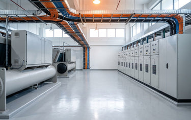
AI-generated industry illustration. No LAPP products depicted.
Which cable schedule covers the building management system, the DCIM feeds and the power monitoring points? Not the one written for the server floor. A data centre's facility layer runs on a different cable plan than the racks, and treating it as an extension of the IT network is how false readings and blind spots get built in. Plant rooms carry electrical noise the white space does not, so shielding and grounding on sensor and instrumentation cable belong in the specification for that environment rather than inherited from the rack cabling plan.
One boundary first, because it saves a conversation later. The high-speed IT network fabric, the 100, 400 and 800G inter-rack switching that connects servers and GPUs, is not what this piece covers and is not LAPP's scope. We said the same thing when we wrote about AI data centre connectivity at the rack. What follows is the layer underneath the white space: BMS, DCIM, power monitoring and cooling plant instrumentation.
Why does the data centre's facility layer need different cable than the server floor?
Because it lives somewhere else. Server-floor cabling sits in a temperature-controlled hall on a structured cabling plan, in trays that carry nothing but data. Facility cabling runs through plant rooms, roof plant and mechanical spaces, past chillers, generators, switchgear and variable frequency drives.
That changes three things in the specification. Electrical noise is the first. A VFD switching a chiller compressor puts noise onto cables routed near it, and a sensor pair with the wrong screen picks it up.
Conditions are the second. Heat, vibration and humidity in a mechanical room are not white-space conditions, and a cable chosen against a data-hall assumption is being asked to do a job it was not selected for.
Mixed traffic on one tray is the third. Facility instrumentation carries analogue sensor signals, digital field-bus traffic and industrial Ethernet, often at different voltage levels, sharing a route. Structured cabling standards written for the server floor do not settle how those coexist.
This is ordinary industrial communication practice, applied to a building most people think of as an IT asset. ETHERLINE® industrial Ethernet cable carries the BMS and DCIM network traffic, and UNITRONIC® control and instrumentation cable carries the sensor and field-bus side. Both are specified by the environment they run through, so confirm the type and its construction against the published product specifications before it reaches a schedule.
What causes false readings in BMS and DCIM sensor networks?
Often the cable, and rarely where anyone looks first. A temperature point that drifts, a flow meter that reports a step change nothing else confirms, a power meter that disagrees with the one upstream of it. The first instinct is to suspect the sensor, then the BMS logic, then the integrator.
Three cable-side causes come up again and again. A screen terminated at one end only when the installation needed it terminated properly at both, or bonded at both when the earthing arrangement could not carry it. A screen left floating at a junction box because the gland was not the type that carries the screen through. And a sensor pair run parallel to a VFD motor cable for twenty metres of shared tray because that was the route the tray took.
None of those fail outright. That is what makes them expensive. The reading is present, plausible and wrong, so the fault gets chased through software and equipment before anyone puts a meter on the cable. We went through the shielding side of this in more detail for EMI hotspots, and a data centre plant room is one.
Two habits take most of it out. Specify the screen and the grounding arrangement in the cable schedule rather than leaving it to the installer, and keep instrumentation separated from drive and power cable at the tray design stage, where separation is free. Retrofitting either one after commissioning is not.
There is a security dimension too, once the BMS reaches beyond the building. Facility networks increasingly get remote access for vendors and monitoring, which puts an OT network in contact with IT, and that is worth designing rather than discovering.
How do you cable power monitoring and cooling plant instrumentation in a data centre?
Start from the route, not the device list. Walk the tray from the plant room to the panel and note what shares it, where it passes a drive or a transformer, where it leaves conditioned space, and where it enters an enclosure. That walk decides more of the specification than the sensor datasheet does.
Power monitoring points are the clearest case. Meters at the switchboard, the busway and the PDU sit inside or beside equipment carrying substantial current, and their communication cable often runs back along the same route. Screened cable and a deliberate grounding arrangement are the specification, not an upgrade.
Cooling plant is the harsher one. Chiller plant rooms, condenser decks and pump rooms put heat, vibration and washdown on the same cable, and rooftop routing adds sunlight and rain to it. Cable selected for a tray in a data hall is not selected for that.
Protocol matters at the point of selection. Modbus over RS-485, BACnet, PROFINET and plain industrial Ethernet each ask something slightly different of the pair count, the screen and the impedance, so the protocol needs to be settled before the cable type is. We covered that selection logic on the ETHERLINE® and PROFINET side, and the same method carries across.
Enclosure entry is where a good schedule often stops short. Every one of these cables enters a panel, a junction box or a field device, and the entry has to hold the seal and, for screened cable, carry the screen through. A SKINTOP® cable gland is specified for that job, against its own datasheet rather than the cable's.
This is the point where cables and connectors have to be specified together rather than bought separately. LAPP designs and manufactures both, which is why the facility cable schedule and the entry hardware can come from one source, with single-source accountability behind them. The data centre pages are the starting point for the range.
How much of this applies varies by facility. A colocation hall in Singapore with plant on a dedicated deck and a converted building in Jakarta with chillers on the roof are not the same cabling problem, even with identical BMS software on top.
Talk to Our Engineers
If you are writing the facility cable schedule for a data centre build or a retrofit, the useful next step is a conversation about the actual routes rather than a catalogue page. Send the plant layout, the monitoring points and the protocols, and our connectivity specialists can work through the cable types with you.
Four details shorten that conversation: the protocols in use on the BMS and DCIM side, what shares the tray with the instrumentation, where the routes leave conditioned space, and the entry arrangement at each panel or field device. Those four turn a general enquiry into a specification.
Talk to our engineers through the LAPP SEA enquiry page and ask for the data centre infrastructure channel. For current catalogues and datasheets, start from the data centre pages or the download centre.


